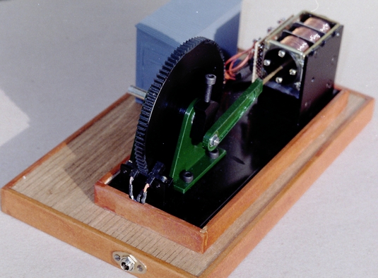
 End view
This project was started off with the series of articles by Gordon Read published in Model Engineer from Sept 1998. This in turn was based on an article from ME published in 1903. Following discussion on the modeleng-list it became obvious that the only way to find out more about the operation of the device was to build one. As a secondary object it should provide an operating exhibit for club displays.
As ever when starting to build a model I looked around my workshop to find the easiest materials to convert into parts. The flywheel (3.5" diam) came from a photocopier as did the solenoid. The baseplate is probably from the same source. My aim was to reduce the power requirement as much as possible so all rotary bearings are ball bearings. More photocopier leftovers!
The solenoid had to be dismantled and rebuilt. Originally it had a single 24V coil. I unwound the coil, split the former into three and inserted two iron dividers then glued it back together. The original wire was then rewound as three separate coils. The frame of the solenoid was then attacked and the iron core which part fills the central tube was drilled out. A hole was drilled in the back of the frame of the same diameter as the central tube. Early experiments showed that although the plunger and interior of the coil former are covered with some low friction coating they actually produced a great deal of friction. Hence the use of black plastic end covers to act as guides for the piston rod. The plunger was cut into two pieces of different lengths and both were drilled through the centre to take the piston rod. In order to avoid rubbing on the inside of the coil former I turned the pieces down slightly while held between centres . Experiments were conducted to find which of the two lengths worked best. It seemed the longer was slightly better. It is about the same length as one of the coils, 15mm.
End viewHaving converted the solenoid, and decided on the length of the piston it was easy enough to work out the crank throw and make the crank. The connecting rod was originally just a piece of bent wire so that it could be modified quickly. Once I was happy with it I fabricated a more solid looking item from plastic sheet.
Initial testing was conducted using a variable frequency 4 phase drive with each phase on for one eighth of a revolution. the second and forth phase are both used to drive the centre coil. The results were unsuccessful. The wheel could sometimes be made to continue to rotate when started by hand but as soon as any attempt was made to vary the frequency the coils pulsed out of sync with the position of the piston. Despite the heavy flywheel the result was often immediate slow down and jittering backwards and forwards. Obviously the power was available but it needed better control.
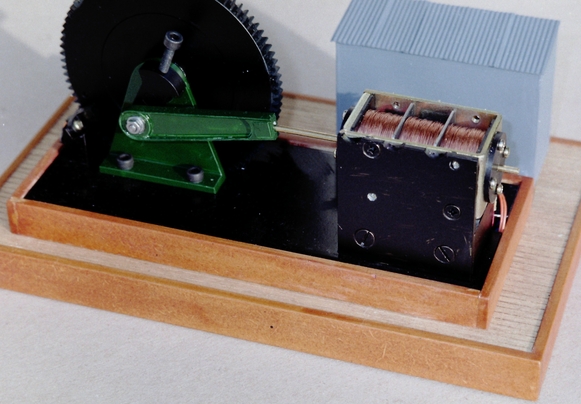
As luck would have it the flywheel was originally a gear wheel and had 86 teeth on the periphery. Two methods of sensing the teeth were tried. The first using a hall effect sensor was not successful so a photodetector was cut in half and mounted either side. With careful adjustment of the position a reasonable pulse was produced which was amplified to produce a square wave with a fast rise time. The detector can be seen on the baseplate at the opposite end of the flywheel to the coils.
 Back view
Ok so now I knew how far the flywheel had rotated but I still didn't have any way of telling the absolute position of the crank. A second photodetector was used to sense a small hole in the flywheel. This sensor is mounted under the baseplate. At this point it became obvious that a microcontroller was needed to tie all the control and drive signals together. Enter a PIC 16F84 microcontroller. This had some spare input/output pins so a display and keypad were added to make diagnostic work easier. This is housed in the grey 'hut' in front of the coils. Writing the software and debugging it probably took longer than constructing the model and it is not finished yet. However enough worked to exhibit it in our local Model Railway Exhibition at which the Stroud Model Engineers had a stand.
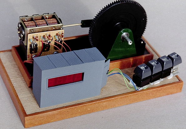 Front view
The unit has worked continuously for 7 hours on two days at a speed of around 200rpm. It can be controlled from around 40 to 700 rpm by means of the keypad. It would be able to go slower if the flywheel was balanced better. (note the 4mm hex head screw adding weight to the crank) To start rotation only requires a push into one coils operating position. The engine will then gradually pick up speed. RPM is displayed on the 4 digit display in the 'hut' window. Just like a steam engine the timing has to be set up with the crank being set at a particular angle to the hole in the flywheel. Unlike a steam engine you can set the position that each coil fires at by using the keypad. This allows you to set the speed and fine tune the timing.
Results are encouraging. The engine runs off a 9V AC adaptor. All the electronics is supplied with a regulated 5V and only the solenoids run direct from the 9V. Current consumption averages out at about 0.25A including the LED displays. The coils do not even get noticeably warm. With more work on the magnetic circuit this could be reduced still further or mechanical power takeoff could be attempted. There is no doubt that incorporating the microcontroller has converted a temperamental fixed speed unit into a flexible and docile unit which could be developed further.