This is a hot air engine I constructed over a fortnight when recuperating from Flu. Some of the parts had been cluttering up the workshop for a year or more waiting for a suitable moment to start the construction. The design is very much influenced by the Sterling Engine Society. Those of you who attend M.E. exhibitions in the UK will be familiar with their stand. It is always one of the most active displays at any exhibition. Hot air engines have a special fascination to some model engineers partly because it is not always obvious why they work. Hence the stand is invariably surrounded by people asking for explanations. The engine I have built here falls right into that category.
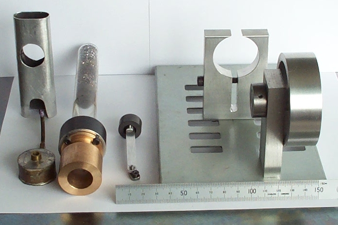
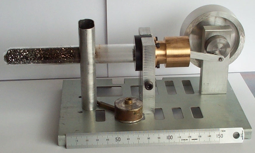
This is not a design built from a kit or even to any detailed plans. The proportions come from looking at models at exhibitions and reading the Sterling Engine Society newsletter. It is all based around the size of the glass tube. Mine is a test tube which is handy as one end needs to be sealed anyway. The internal diameter is around 16mm and the length about 150mm. The tube is held in its support by O rings and the cylinder is also sealed to the support by an O ring. The support is clamped to the stand to enable the tube position to be adjusted when the stroke is altered. When I first built it the piston was poly acetal and the cylinder cast iron. Although there was a good seal the friction was too high. When the flywheel was rotated it very quickly stopped. After taking advice I change the piston to graphite and the cylinder to phosphor bronze. Now when the flywheel is rotated it continues for many revolutions before stopping.
The flywheel and crank disc are mounted on a shaft which rotates in ball races. The connecting rod also has ball bearings at the ends. Both stands are mounted on a plate which is currently a 2mm thick steel cover from a laser printer power supply. It doesn't look good and in operation you can see it flexing so it will get replaced when I find something suitable.
The meths burner is from a previous project but it provides a small flame at just the right height so was pressed into service. The chimney is a flattened ally tube. It is probably not necessary for domestic running but does help in an exhibition hall where draughts can cause problems.
Inside the test tube is part of a stainless steel scouring pad. In the photograph there is also a small plug of steel wool. This was mainly to stop the scouring pad wandering down the tube.
Initial trials were not very encouraging. The engine had plenty of compression but there was no noticeable urge to continue rotating. I took it to the Bristol Model Engineering Exhibition at Thornbury and consulted the experts. Bob Sier had a play and offered some suggestions. I remade the piston and cylinder overnight and took it back again the next day. I had managed to get it to revolve slowly while at home but back at the exhibition it proved troublesome. Eventually with a bigger burner a few revolutions at very low speed were coaxed out of it. Back home after the exhibition I tried some experiments, changing the stroke, adding more regenerator material and reducing the dead space between the piston and the heated part of the tube.
The stroke is fairly important. The engine works best with as high a compression ratio as the structure can take. It doesn't stop working if the stroke is reduced but it does take longer to start.
The quantity of regenerator material did not seem very critical nor the position of the flame, as long as it is somewhere near the end of the regenerator.
What made the biggest change was putting a plug of steel in the neck of the test tube. On advice from Bob Sier I tried a restrictor first but this had no obvious effect so I wondered if actually reducing the volume of air between the piston and the heater might help. Anything solid in the tube will of course increase the compression ratio but would it allow more work to be extracted from the air? The answer seems to be yes at least in the short term.
After many trials I managed to get it to start about 1 minute after lighting the burner. It would then gradually increase speed to around 240rpm. When fully warmed up it is self starting in all but dead centre positions. Of course you have no way of knowing which way it will end up rotating.